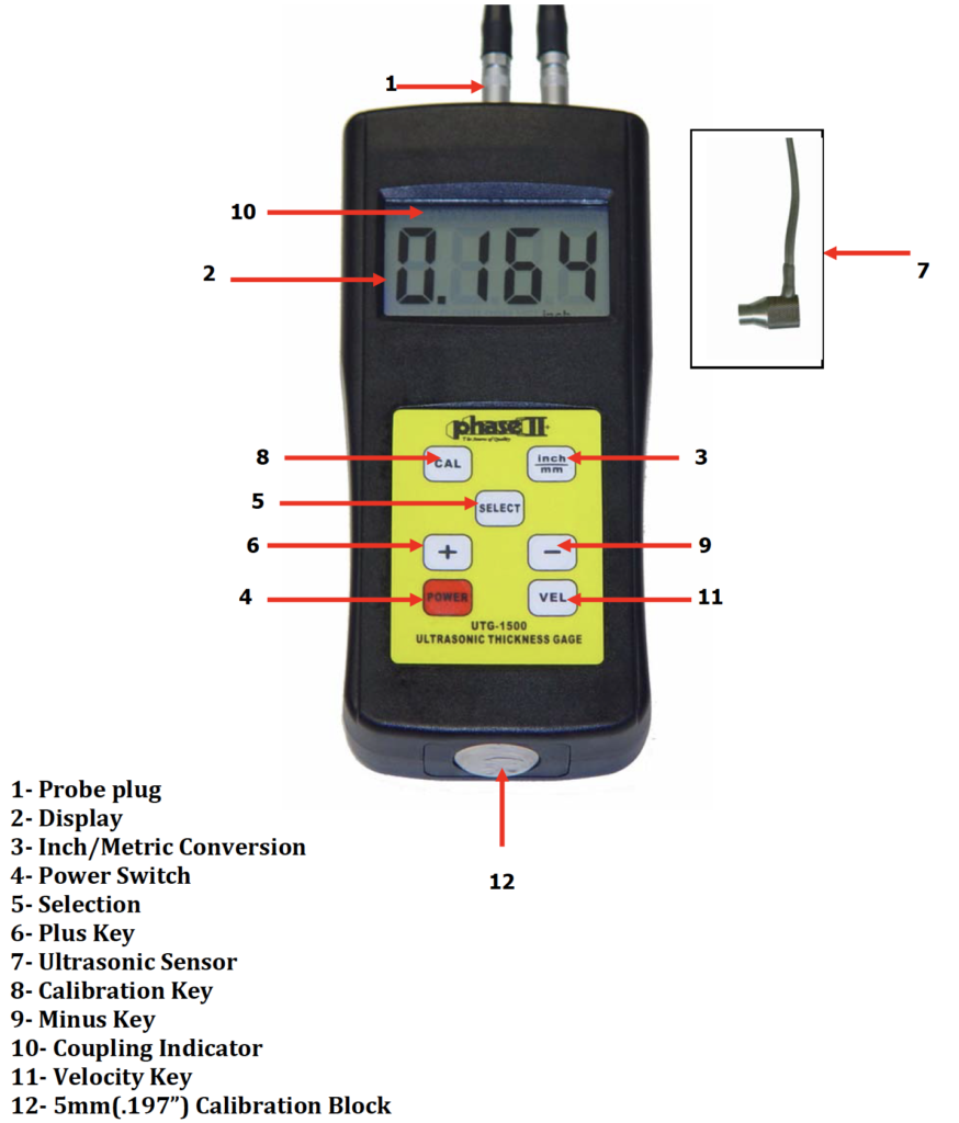
The UTG‐1500 is an advanced lightweight ultrasonic thickness gauge that is designed to be convenient to use and rugged enough to operate in harsh environments.
- Utilizing the latest in micro computer circuitry, this unit offers a combination of high accuracy and quick measurement time.
- Offers a wide measuring range coupled with high resolution.
- Capable of measuring any material that sounds waves can travel through as long as the object has parallel top and bottom surfaces.

Calibration
1) Place a small drop of coupling gel on the calibration block #12 test block on the bottom of the gage.
2) Push the calibration key #8 and “cal” will flash on the display.
3) Press the #7 probe on the #12 calibration block making sure the coupling indicator appears on the display. The reading should be 0.197” (5mm). This will flash with the “cal”. While holding probe on the block, press CAL to save. Remove probe from block. Press the probe on the test block again to confirm the reading is approx. 0.197”.
4) The calibration result will automatically be saved once confirmed. This procedure lets you know that the unit is functioning properly. Now it is time to set the UTG‐1500 to read your part/material correctly.
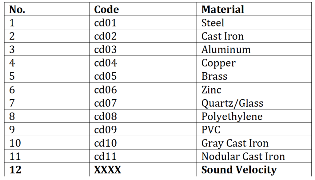
Material Selection
1) Press the “Select” button to enter the material selection state and press the + button to choose from 11 common materials. Please see chart below for material listings. The display will show the code only(cd01) as you toggle through the material selection process. Press the Select button to confirm the selection.
Measuring Procedure
1) Press the Power switch to turn unit ON
2) Press IN/MM button to set Inch/mm
3) Add a drop of gel to surface to be tested and place the probe directly into the gel. The reading on the display is the actual thickness of the part being measured.
4) The last reading is held on the display until the unit is powered off.
Preparation
The gauge is capable of performing measurements on a wide range of materials, from various metals to glass and plastics. Different types of material, however, will require the use of different transducers. Choosing the correct transducer for a job is critical to being able to easily perform accurate and reliable measurement. The following paragraphs highlight the important properties of transducers, which should be considered when selecting a transducer for a specific job. Generally speaking, the best transducer for a job is one that sends sufficient ultrasonic energy into the material being measured such that a strong, stable echo is received by the gauge. Several factors affect the strength of ultrasound as it travels.
Initial Signal Strength
The stronger a signal is to begin with, the stronger its return echo will be. Initial signal strength is largely a factor of the size of the ultrasound emitter in the transducer. A large emitting area will send more energy into the material being measured than a small emitting area. Thus, a so‐called “1/2 inch” transducer will emit a stronger signal than a “1/4 inch” transducer.
Absorption and Scattering
As ultrasound travels through any material, it is partly absorbed. If the material through which the sound travels has any grain structure, the sound waves will experience scattering. Both of these effects reduce the strength of the waves, and thus, the gauge’s ability to detect the returning echo. Higher frequency ultrasound is absorbed and scattered more than ultrasound of a lower frequency. While it may seem that using a lower frequency transducer might be better in every instance, low frequencies are less directional than high frequencies. Thus, a higher frequency transducer would be a better choice for detecting the exact location of small pits or flaws in the material being measured.
Geometry of the Transducer
The physical constraints of the measuring environment sometimes determine a transducer’s suitability for a given job. Some transducers may simply be too large to be used in tightly confined areas. Also, the surface area available for contacting with the transducer may be limited, requiring the use of a transducer with a small wear face. Measuring on a curved surface, such as an engine cylinder wall, may require the use of a transducer with a matching curved wear face.
Temperature of the Material
When it is necessary to measure on surfaces that are exceedingly hot, high temperature transducers must be used. These transducers are built using special materials and techniques that allow them to withstand high temperatures without damage. Additionally, care must be taken when performing a “Probe‐Zero” or “Calibration to Known Thickness” with a high temperature transducer.
Selection of the proper transducer is often a matter of trade offs between various characteristics. It may be necessary to experiment with a variety of transducers in order to find one that works well for a given job. The transducer is the “business end” of the instrument. It transmits and receives ultrasonic sound waves that the instrument uses to calculate the thickness of the material being measured. The transducer connects to the instrument via the attached cable, and two coaxial connectors. When using transducers, the orientation of the dual coaxial connectors is not critical: either plug may be fitted to either socket in the instrument. The transducer must be used correctly in order for the instrument to produce accurate, reliable measurements. Below is a short description of the transducer, followed by instructions for its use.

Above Left figure is a bottom view of a typical transducer. The two semicircles of the wear face are visible, as is the barrier separating them. One of the semicircles is responsible for conducting ultrasonic sound into the material being measured, and the other semicircle is responsible for conducting the echoed sound back into the transducer. When the transducer is placed against the material being measured, it is the area directly beneath the center of the wear face that is being measured. Right figure is a top view of a typical transducer. Press against the top with the thumb or index finger to hold the transducer in place. Moderate pressure is sufficient, as it is only necessary to keep the transducer stationary, and the wear face seated flat against the surface of the material being measured.
Condition and Preparation of Surfaces
In any ultrasonic measurement scenario, the shape and roughness of the test surface are of paramount importance. Rough, uneven surfaces may limit the penetration of ultrasound through the material, and result in unstable, and therefore unreliable, measurements. The surface being measured should be clean, and free of any small particulate matter, rust, or scale. The presence of such obstructions will prevent the transducer from seating properly against the surface. Often, a wire brush or scraper will be helpful in cleaning surfaces. In more extreme cases, rotary sanders or grinding wheels may be used, though care must be taken to prevent surface gouging, which will inhibit proper transducer coupling.
Extremely rough surfaces, such as the pebble‐like finish of some cast iron, will prove most difficult to measure. These kinds of surfaces act on the sound beam like frosted glass on light, the beam becomes diffused and scattered in all directions.
In addition to posing obstacles to measurement, rough surfaces contribute to excessive wear of the transducer, particularly in situations where the transducer is “scrubbed” along the surface. Transducers should be inspected on a regular basis, for signs of uneven wear of the wear face. If the wear face is worn on one side more than another, the sound beam penetrating the test material may no longer be perpendicular to the material surface. In his case, it will be difficult to exactly locate tiny irregularities in the material being measured, as the focus of the sound beam no longer lies directly beneath the transducer.
Important Notes
When the tool is displaying thickness measurements, the display will hold the last value measured, until a new measurement is made. In order for the transducer to do its job, there must be no air gaps between the wear‐face and the surface of the material being measured. This is accomplished with the use of a “coupling” fluid, commonly called “couplant”. This fluid serves to “couple”, or transfer, the ultrasonic sound waves from the transducer, into the material, and back again. Before attempting to make a measurement, a small amount of couplant should be applied to the surface of the material being measured. Typically, a single droplet of couplant is sufficient.
After applying the couplant, press the transducer (wear face down) firmly against the area to be measured. The coupling status indicator should appear, and a digit number should appear in the display. If the instrument has been properly “zeroed” and set to the correct sound velocity, the number in the display will indicate the actual thickness of the material directly beneath the transducer.
If the coupling status indicator does not appear not stable, or the numbers on the display seem erratic, check to make sure that there is an adequate film of couplant beneath the transducer, and that the transducer is seated flat against the material. If the condition persists, it may be necessary to select a different transducer (size or frequency) for the material being measured.
While the transducer is in contact with the material that is being measured, the instrument will perform four measurements every second, updating its display as it does so. When the transducer is removed from the surface, the display will hold the last measurement made.
Note
Occasionally, a small film of couplant will be drawn out between the transducer and the surface as the transducer is removed. When this happens, the gauge may perform a measurement through this couplant film, resulting in a measurement that is larger or smaller than it should be. This phenomenon is obvious when one thickness value is observed while the transducer is in place, and another value is observed after the transducer is removed. In addition, measurements through very thick paint or coatings may result in the paint or coating being measured rather than the actual material intended. The responsibility for proper use of the instrument, and recognition of these types of phenomenon, rests solely with the user of the instrument.
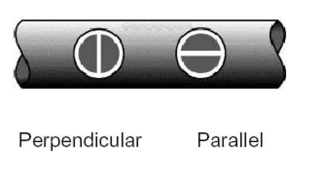
Measuring Pipe and Tubing
When measuring a piece of pipe to determine the thickness of the pipe wall, orientation of the transducers is important. If the diameter of the pipe is larger than approximately 4 inches, measurements should be made with the transducer oriented so that the gap in the wear face is perpendicular (at right angle) to the long axis of the pipe. For smaller pipe diameters, two measurements should be performed, one with the wear face gap perpendicular, another with the gap parallel to the long axis of the pipe. The smaller of the two displayed values should then be taken as the thickness at that point.
Measuring Hot Surfaces
The velocity of sound through a substance is dependent upon its temperature. As materials heat up, the velocity of sound through them decreases. In most applications with surface temperatures less than about 100, no special procedures must be observed. At temperatures above this point, the change in sound velocity of the material being measured starts to have a noticeable effect upon ultrasonic measurement. At such elevated temperatures, it is recommended that the user perform a calibration procedure on a sample piece of known thickness, which is at or near the temperature of the material to be measured. This will allow the gauge to correctly calculate the velocity of sound through the hot material.
When performing measurements on hot surfaces, it may also be necessary touse a specially constructed high‐temperature transducer. These transducers are built using materials which can withstand high temperatures. Even so, it is recommended that the probe be left in contact with the surface for as short a time as needed to acquire a stable measurement. While the transducer is in contact with a hot surface, it will begin to heat up, and through thermal expansion and other effects, may begin to adversely affect the accuracy of measurements.
Measuring Laminated Material
Laminated materials are unique in that their density (and therefore sound velocity) may vary considerably from one piece to another. Some laminated materials may even exhibit noticeable changes in sound‐velocity across a single surface. The only way to reliably measure such materials is by performing a calibration procedure on a sample piece of known thickness. Ideally, this sample material should be a part of the same piece being measured, or at least from the same lamination batch. By calibrating to each test piece individually, the effects of variation of sound‐velocity will be minimized.
An additional important consideration when measuring laminates, is that any included air gaps or pockets will cause an early reflection of the ultrasound beam. This effect will be noticed as a sudden decrease in thickness in an otherwise regular surface. While this may impede accurate measurement of total material thickness, it does provide the user with positive indication of air gaps in the laminate.
Suitability of Materials
Ultrasonic thickness measurements rely on passing a sound wave through the material being measured. Not all materials are good at transmitting sound. Ultrasonic thickness measurement is practical in a wide variety of materials including metals, plastics, and glass. Materials that are difficult include some cast materials, concrete, wood, fiberglass, and some rubber.
Couplants
All ultrasonic applications require some medium to couple the sound from the transducer to the test piece. Typically a high viscosity liquid is used as the medium. The sound used in ultrasonic thickness measurement does not travel through air efficiently.
A wide variety of couplant materials may be used in ultrasonic gauging. Propylene glycol is suitable for most applications. In difficult applications where maximum transfer of sound energy is required, glycerin is recommended. However, on some metals glycerin can promote corrosion by means of water absorption and thus may be undesirable.
Other suitable couplants for measurements at normal temperatures may include water, various oils and greases, gels, and silicone fluids. Measurements at elevated temperatures will require specially formulated high temperature couplants.
Inherent in ultrasonic thickness measurement is the possibility that the instrument will use the second rather than the first echo from the back surface of the material being measured while in standard pulse‐echo mode. This may result in a thickness reading that is TWICE what it should be. The Responsibility for proper use of the instrument and recognition of these types of phenomenon rests solely with the user of the instrument.
Maintenance
REPLACING THE BATTERIES
Once the low battery indicator appears on the screen, the batteries should be replaced.
Use the following procedure when replacing the batteries. Power unit off or wait until the unit turns off automatically. Open the battery compartment. Remove the used batteries and insert new batteries into the compartment, paying close attention to the polarity of the battery.