Holiday Detection
The premature corrosion of a substrate is usually due to a coating failure which is largely from flaws in the finished coating. Holiday tests are used to detect holes, known as holidays or breaks, in a coating. Holiday testing allows the detection of even the smallest coating flaws invisible to the naked eye.
Holiday detection equipment offered by USI is safer, faster and more reliable than ever before. There are various kinds of holiday detectors on the market today, but high voltage holiday tests, or porosity techniques, is ideal for inspecting pipelines and other protective coatings.
The Tinker & Rasor Model APS Holiday Detector is an all-purpose electrical inspection instrument which maintains a given inspection voltage despite the electrical load on the circuit, this is also known as DC pulse holiday detection. This specific model supplies 800V to 35kV in one instrument with two ranges of 3,500V to 35,000V and a low range of 800V to 8,000V. It is recommended for use on any pipe diameter as well as on flat surfaces.
Unpacking and Set-up
Inspection should be made upon receipt to ensure that all parts were received unscathed and every piece of your equipment is in working order. First remove all accessories from the shipping carton, then connect the high voltage wand handle to the front of the instrument and ground cable to the detector handle by inserting it and twisting it clockwise. Never connect or disconnect the cable or wand when the instrument is turned on.
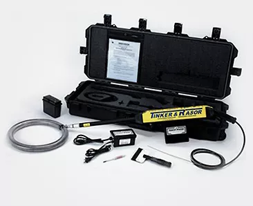
Ensure all the accessories are in the kit by going through the following checklist:
- APS instrument
- Mil-spec waterproof carrying case
- 4″ rubber paddle electrode
- Voltage adjusting screwdriver
- Instruction manual
- One electrode (3 versions to choose from)
- Compax connector for full circle electrodes
- 20′ ground cable
- Battery charger
- Two batteries
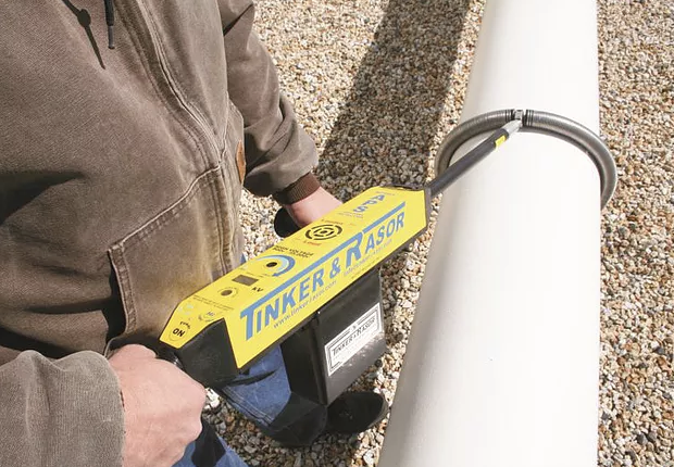
Next attach the electrode to the high voltage wand handle assembly and apply it to the structure to be inspected. The electrode should always make close contact with the surface under inspection. From this point the detector is ready to turn on and test. Turn it on by holding the safety switch handle firmly against the instrument handle, where the rubber grip is located, and then press the on button. The holiday detector will turn off when the safety handle is released. The three choices listed in the kit are as follows with more choices to attach sold separately:
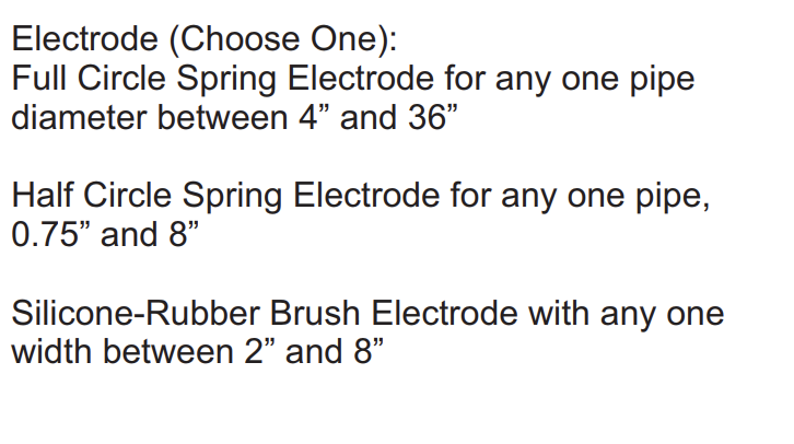
Electrodes
Full and half circle electrode springs are made stainless steel for resistance to roll down pipe. Half circle springs have 190-degree arc. These types of electrodes are ideal for inspecting pipeline coatings in a plant or the field. These are square cut and tightly wound for tight fit and intimate contact to coatings and will inspect the entire coated surface of the pipe in one pass.
Silicone-rubber electrodes are made of conductive material with very low resistivity, a unique combination of silicone rubber and carbon. It meets many different requirements and applications and it is used to inspect welds, tanks, rail cars, concrete structures or other conductive substrates with non-conductive coatings.
Wire brush electrodes are made of crimped stainless steel. It meets many different requirements and applications, especially for coated surfaces that are uneven or include fittings, bolts, or other tight corners need to be inspected. It is best used for coatings with irregular surfaces or joints, fittings, ect.
Sponge electrodes are only used with low voltage holiday detectors for rapid wetting.

Operation
Once you turn the holiday detector on you can adjust the voltage using the screwdriver supplied in your kit after pushing the high or low setting buttons to pick your range. The voltage you should use is dependent on the dielectric strength and thickness of the coating being tested or the test method or standard you are working to. Please see the voltage section for details.
After adjusting the voltage recommended for your substrate, attach the ground cable to the holiday detector. If after running the test all seems well get ready to contact the electrode to the substrate surface. If not you may need to clip the ground cable to an uncoated section of the substrate being tested. When testing on concrete, either hammer a masonry nail or conducting spike into the concrete, or use any exposed uncoated rebar. In some instances, you can simply use a grounding mat as a larger trailing lead, aiding in the grounding when in drier conditions, depending on the substrate. The grounding cable alone should work fine in most cases unless the environment is very dry.
Place the live electrode on the test surface and move it over the work area at a constant speed, as defined by the test method or standard you are working to. Always be sure to switch off the instrument before disconnecting any cables. The speed of the electrode’s travel along the pipe should never be excessive, since faulty inspection may result.
Testing
Occasional checks of the detector operation should be made, particularly if no holidays are being found. This can be accomplished by testing for the spark and signal at the degree of the coating where bare pipe exists or by touching the probe end to the bare pipe and noting the length of the spark and the visual and audible signal effectiveness. If the visual and audible signal do not both occur when the spark discharges from the electrode into a known holiday, the ground return (path between the metallic pipe and earth and the earth to the ground trail of the detector) is of high resistance. In this case, a better ground is required and a direct grounding is extremely uncommon unless the soil is very dry or the detectors output is low.
Voltage
The voltage used to test should be high enough so that in areas where the coating is electrically weaker, due to a flow or discontinuity, there is sufficient voltage to break down the gap or insulation between the probe and the substrate. When this breakdown occurs the current flows from the probe, through the substrate and back into the holiday detector, completing a circuit and thereby triggering an alarm to signal a flaw has been detected. As the high voltage method can locate any area where the coating is weaker than specified, this method allows you to detect flaws that don’t go all the way down to the substrate, such as cratering for example, as well as voids within the coating.
The Tinker & Rasor APS Holiday Detector includes an integrated voltmeter displayed on the front panel of the main instrument. The LCD screen of the voltmeter measures and displays the output voltage of the holiday detector. This display gives the user the ability to tune the APS to a specific voltage with in increment in 100V steps.
Correct voltage output for a given thickness of coating has long been a matter of controversy. However, recent formulas have been suggested which may be used as a guide for correct peak voltages on various coating thickness. The calculation is as follows:
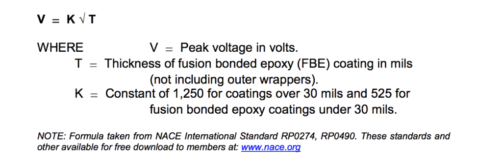
These formulas, when applied to a coating of 3/32” thickness and with a constant of 1,250, would indicate an applied voltage of 12,500 volts peak or a coating of 16 mil thickness with a constant of 525 would indicate an applied voltage of 2,100 volts. A common practice used in setting inspection voltages in the field is to adjust the output voltage by visual observation. It is the consensus that spark discharge at least twice the thickness of the coating will give adequate inspection voltage and compensate for determining inspection voltage, it should be done while the electrode is in the normal operating position and under actual grounding conditions.
Calibration
The model APS voltmeter is accurate to +/- 5% of the output voltage, as shown on the LCD display on the instrument panel. It is recommended that this model follow an annual calibration cycle to ensure the instrument is in good working order and that the LCD of the integration voltmeter is accurate.
Battery Charging
The Model APS comes with two batteries. The lithium-ion battery should be charged after each use. The Model APS will indicate when the battery voltage is low, by a slow blinking of the Green Power LED, instead of providing a steady glow. The battery charger has an LED. RED color LED indicates the battery is being charged. GREEN color LED indicates that battery is fully charged. GREEN color LED also means that the battery is on trickle charge, and can be left in this condition. The charger can be used with 110v / 240v AC. It is an auto sensing charger that can be used throughout the world. Please consult your manual if you have a battery with a serial number prior to 827.
Grab your holiday detector today to start inspecting your coatings. USI also offers training and expert technical support.